


Send Message
Privacy statement: Your privacy is very important to Us. Our company promises not to disclose your personal information to any external company with out your explicit permission.

FARIZON MOTOR TECHNOLOGY CO.,LTD
Before officially entering the construction site, the primary task is to complete the on-site survey, confirm the networking requirements, and avoid rework in the later stage. Firstly, calculate the total power and load type of the load, distinguish between constant load and impulse load, and determine the number of networked units and the power ratio of each unit. Power networking is not simply about connecting multiple engines together. The models, speeds, and voltage levels between the units need to be matched. Priority should be given to selecting FARIZON engine units of the same series and specifications to reduce the difficulty of parallel connection.
Next, investigate the site environment. It is necessary to measure the space in the computer room or equipment area, reserve maintenance channels for the units, and provide ventilation and heat dissipation space; Assess environmental temperature, dust, and humidity, and determine noise reduction, dust prevention, and rain protection plans. At the same time, confirm the grounding conditions. The power networking system has strict requirements for grounding resistance, and poor grounding can bring signal interference and leakage risks.
Finally, draw the installation drawings, clarify the placement of the unit, the direction of the power cables, the routing of communication lines, the installation points of the control cabinet, and sort out the safety isolation plan. After the completion of the plan, check the list of accessories, including generator sets, grid connected control cabinets, synchronization modules, communication cables, transformers, grounding devices, etc. Check that all equipment has a good appearance and complete certificates of conformity.
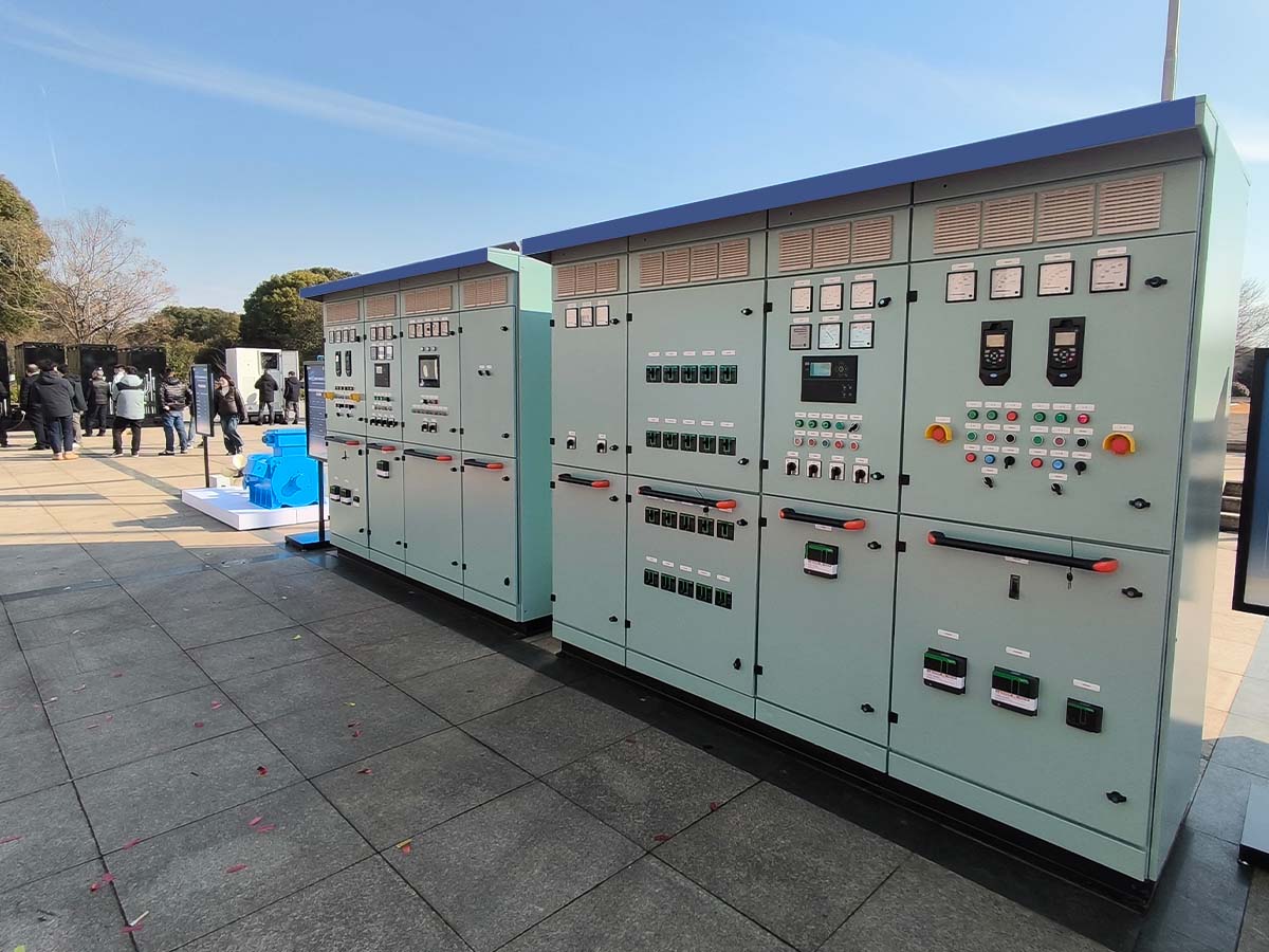
The survey and scheme confirmation have been completed, and we have entered the hardware installation phase. Arrange each engine generator set according to the blueprint, leaving a safe distance between the units for easy maintenance and upkeep in the future. The base of the unit needs to be treated with shock absorption, and shock pads should be installed to reduce the transmission of operating vibrations, prevent vibration from pulling cables, and avoid affecting the stability of communication signals. The unit should be placed horizontally, the levelness should be corrected, and the base bolts should be fixed.
After fixing the unit, install the power networking core control cabinet. The control cabinet should be installed in a dry, easy to operate and observe location, away from high-temperature exhaust vents. Install synchronous controllers, air switches, protective devices, and current and voltage transformers inside the cabinet. When installing transformers, pay attention to the direction, isolate the primary and secondary lines, strictly distinguish between strong current circuits and weak current signal circuits, and prevent strong current interference with control signals, which may cause unit synchronization failure.
Synchronize the construction of supporting pipelines, arrange the engine exhaust pipeline and Fuel pipeline according to specifications, and provide insulation treatment for the exhaust pipeline to avoid high temperature baking of cables; The fuel pipeline joint is sealed in place to eliminate the hidden danger of oil leakage.
Cable construction is a highly error prone link in the installation of power networking, and power cables and communication signal lines must be routed separately. Power cables carry high currents, and cables that meet current carrying requirements should be selected. Cable laying should maintain a suitable bending radius, cable joints should be firmly crimped, and insulation protection should be done well. Communication cables are used for data exchange between units and between units and control cabinets, transmitting signals such as speed, voltage, and load. It is recommended to use shielded communication cables with a single point grounding on the shielding layer to reduce external electromagnetic interference.
The grounding system is the safety bottom line. All metal bases of generator sets, control cabinet shells, and transformer shells must be connected to a unified grounding grid and tested using a grounding resistance tester. The grounding resistance must meet the design standards. Separate the working grounding and protective grounding, and do not simply overlap them on metal pipes. After all wiring is completed, check the wiring labels one by one, verify the wire numbers, and prevent misconnections or false connections.
All hardware installation is completed, debris on site is cleared, pre power on inspection is carried out to confirm that there are no short circuits or wiring errors, and then step-by-step debugging is carried out. The first step is single machine testing. Start each FARIZON engine unit separately, check the operating status of the individual unit, observe whether the voltage, frequency, and speed are stable, check whether the alarm function is normal, and conduct network debugging after the individual unit has no faults.
Step 2: Multi machine synchronous debugging. Start the host and wait for it to run stably. Set the network controller parameters, including voltage, frequency, phase threshold, and load distribution ratio. Integrate the slave into the system, observe the synchronization controller data, and verify phase synchronization. The system will automatically allocate electricity load, test load fluctuation scenarios, and check whether the unit can automatically increase or decrease output to avoid overloading of a single unit.
The third step is to test the protection function. Simulate fault scenarios such as overload, voltage loss, overspeed, and communication interruption to verify the system protection logic. When a fault occurs, the system should be able to automatically alert and isolate the faulty unit, while the other units maintain power supply to ensure power continuity. Repeatedly test multiple times to ensure the reliability of all protective actions.
After all the debugging meets the standards, the overall acceptance work will be carried out. Organize installation drawings, wiring records, debugging reports, and keep archives. Continuously conduct a trial run with load for a period of time, continuously monitor the network operation parameters, confirm that the multi machine cooperation is stable, and there are no abnormal vibrations, noises, or alarm messages.
Throughout the installation process of the power network, it is necessary to comply with the safety regulations for high-voltage operations, and arrange certified personnel to operate during the power on commissioning stage. After the system installation is completed, provide basic training to the on-site operators to familiarize them with the system start stop logic and basic alarm handling methods.
Power networking transforms multiple engines into a collaborative energy supply system, and the installation quality directly determines the reliability of the entire system. From early planning and hardware deployment to cable construction and joint debugging, every step needs to be rigorously executed in order to fully leverage the advantages of multi unit parallel connection and achieve stable, safe, and intelligent distributed power supply.
Email to this supplier
Privacy statement: Your privacy is very important to Us. Our company promises not to disclose your personal information to any external company with out your explicit permission.
Fill in more information so that we can get in touch with you faster
Privacy statement: Your privacy is very important to Us. Our company promises not to disclose your personal information to any external company with out your explicit permission.